


Questions this guide answers
Primary question: How different is stated battery runtime from runtime with brushes, vacuum, turns and normal soil?
- How should a buyer test loaded floor-scrubber runtime on a representative route?
Direct Answer
A useful floor-scrubber runtime test operates the exact quoted unit with traction or drive, the normal brush or pad, solution delivery and dirty-water recovery active on a representative route. Start from a documented full-charge condition, repeat a fixed route cycle, record every working and stopped interval, and end at a pre-agreed machine or route boundary without forcing the battery beyond approved limits. For this buyer-defined protocol, plan two valid recorded runs when practical and compare the lower result with the buyer's required loaded work time and reserve, rather than converting a published hour range into a shift guarantee.
Decision-page companion
Start with the short decision guide
Use the comparison guide for screening and this protocol for an exact-configuration loaded-route test.
Compare Runtime, Tanks, Width and Practical ProductivityScope and assumptions
This is a machine-level duty-cycle protocol. It tests how long the complete supplied system performs the buyer's work under recorded conditions. It is not a laboratory battery-capacity test, a battery-life or cycle-life prediction, a charger certification, or proof that every unit of the same model will deliver the same result.
The method assumes the route is permitted by the machine instructions and the facility. Do not introduce slopes, hazardous locations, extreme temperatures, deep discharge, unapproved opportunity charging or unapproved chemistry merely to make the trial harder. Follow the battery, charger, machine and site safety instructions throughout.
Separate four time questions
Catalog comparisons often use the word "runtime" for different measurements. Define all four before testing.
| Metric | Definition | Procurement use |
|---|---|---|
| Net loaded operating time | Time when the required machine systems are operating on the defined route, excluding only pauses the test plan explicitly excludes | Tests whether the powered system covers the required work block |
| Gross route time | Clock time from route start to route completion, including refill, drain, inspection, debris removal and normal service stops | Tests whether the route fits the real cleaning window |
| Recharge turnaround | Time from connection to the approved charger until the documented ready condition for the next duty cycle | Tests shift handover and power planning |
| Battery service life | Capacity and condition over many cycles and time | Requires a separate long-term protocol; one runtime trial cannot prove it |
A machine may pass net loaded runtime and still fail the gross route window because refill or drain points are too far away. It may also complete one new-battery trial without proving future battery life. Keep these conclusions separate.
Freeze the unit, battery and charger identity
Complete the configuration record before charging. If a required field is not available, mark it as unverified and do not compare the result with a differently documented unit.
| Field group | Required entries |
|---|---|
| Machine | Brand, exact model, serial number, hardware or software revision if shown, hour meter and sample status |
| Battery | Manufacturer, model, chemistry, quantity, nominal voltage, rated Ah or Wh, installation date and cycle count if available |
| Charger | Manufacturer, model, input rating, output profile, software setting if applicable, connector and approved battery match |
| Working configuration | Brush or pad type and condition, pressure or mode, vacuum/recovery setting, solution-flow setting, accessories and payload |
| Route | Floor, soil, cleanable area or distance, turns, stops, joints, permitted slope, traffic and service-point locations |
| Environment | Ambient temperature, floor temperature where relevant, ventilation and any battery temperature available from an approved display or data log |
| End point | Required route complete, approved low-charge warning, normal machine shutdown, minimum accepted state of charge, performance boundary or safety stop |
Do not calculate nominal battery energy from incomplete values. Amp-hours alone do not identify usable energy without voltage, configuration, discharge conditions and system limits. Likewise, a dashboard percentage should not be assumed linear or independently accurate unless its measurement basis is documented.
Define a representative route cycle
Map the real cleaning block into a repeatable cycle. Each cycle should preserve the work that materially loads the system:
- Open straight scrubbing at the normal setting
- Turn-intensive or aisle-end work in both directions
- Edge passes and overlap
- Representative joints, texture and normal soil
- Normal stops for safe maneuvering or traffic control
- Recovery/vacuum operation whenever the intended process requires it
- Solution flow at the approved operating setting
- Refill, drain and debris-removal events at the frequency observed in the route
The buyer may define the cycle by distance, area or time. Distance or area is usually easier to audit because a slower operator cannot make runtime appear longer without also reducing completed work. Mark fixed route points and use the same operator after a practice run. Record turn count, completed cycles and any deviation.
Do not test with the recovery system off if the purchase use requires dirty-water pickup. Do not use a clean, low-resistance floor when the normal route has texture, joints and soil. Conversely, do not introduce an artificial load that is not part of the intended work and then present the result as site runtime.
Pre-test charge and inspection
- Inspect the machine, battery, cable, connector, charger, tanks, brush or pad, squeegee and recovery path according to approved instructions.
- Charge only with the documented approved charger and profile. Record connection time, starting indication, completion indication, charger messages and disconnection time.
- Define "full" using the approved charger or battery-management indication, not elapsed charging time alone.
- Record any rest period after charge and keep it consistent between runs.
- Fill solution using a measured reference and record the chemical and dilution. Empty the recovery tank before the run unless the route method specifies otherwise.
- Photograph the initial machine display and record state of charge, voltage or other approved data that is actually available. Do not invent missing battery fields.
- Confirm the test area's traffic controls, drain, refill point, emergency stop process and observers.
If a new battery requires conditioning, follow the battery manufacturer's written procedure and identify which cycles are conditioning rather than recorded acceptance runs. Do not improvise deep-discharge cycles.
Execute and log the loaded run
Use one shakedown run to stabilize the route and operator technique, then perform two valid recorded runs when practical under this buyer-defined protocol. Report both; do not average away an early shutdown. A different pre-agreed run count is valid when the buyer records the reason and acceptance method.
At route start, synchronize the timer, display photograph and worksheet. Log at each cycle boundary or at a fixed interval:
| Log field | What to record |
|---|---|
| Clock and elapsed time | Start, each checkpoint, service stop, restart and end |
| Work completed | Route segment, cycle, area or distance and pass count |
| Systems active | Drive/traction, brush or pad, recovery/vacuum, solution flow and accessories |
| Battery indication | Displayed state of charge, warning state, voltage or BMS value if available |
| Water cycle | Solution added, recovered volume where measured, refill and drain duration |
| Route load | Turn count, soil change, traffic interruption, debris removal and operator change |
| Performance | Cleaning result, water recovery, speed or power change, noise or vibration change and alarms |
| Environment | Ambient and available battery temperature at agreed checkpoints |
Keep two clocks. Gross time continues through normal route service. Net loaded time pauses only for events the approved plan excludes, such as a test-instrument correction. A normal refill, drain or debris stop belongs in gross route time even if the powered systems are off.
Stop at the first approved end point. Examples are completion of the required route with reserve remaining, a normal low-charge or machine shutdown boundary, inability to sustain the required cleaning or recovery result, a battery or charger warning, an unsafe temperature or condition, or the maximum test window. Never bypass a protective limit to obtain a longer number.
Calculations and worksheet
Use these definitions:
Net loaded time = end time - start time - approved excluded pauses
Gross route time = end time - start time
Runtime margin (%) = (lower valid net loaded time - required net loaded time) / required net loaded time x 100
Route completion margin must also account for tank service and other gross-time events. A positive net-runtime margin does not rescue a route that misses the reopening or shift deadline.
Illustrative example
This example is illustrative only and is not an ELEREIN result.
A buyer requires 3 h 45 min of loaded operation and pre-approves three reserve bands: at least 10% for pass, 5% to less than 10% for conditional hold and below 5% for fail. Two valid runs produce 4 h 18 min and 4 h 05 min of net loaded operation. Use the lower run: 4 h 05 min = 245 minutes, while required loaded time is 225 minutes.
Runtime margin = (245 - 225) / 225 x 100 = 8.9%
The machine completed the route, but it does not meet the buyer's 10% reserve. The result is conditional, not pass. The buyer can revise the route, change an approved configuration, add an operating break supported by the charging plan, or repeat under a justified representative condition. It should not be rounded up to a four-hour-plus guarantee.
If a test stops early with 30% shown on the display, do not divide elapsed time by 70% to project total runtime. Displayed state of charge may be nonlinear, and the untested final portion may behave differently under load.
Data-quality gate
Before applying acceptance logic, decide whether the run is valid.
A run is invalid when the battery or charger identity is unknown, the charge was interrupted or undocumented, required systems were disabled, the route or operator changed materially, the solution setting was altered without control, the floor was not representative, a measurement device failed, or an unplanned repair changed the unit. Invalid means no decision. It is not a conditional pass.
Normal operational events are not automatically invalid. A refill, drain, debris blockage or traffic delay may be exactly what the test is meant to capture. Log it and classify it according to the approved plan.
Pass, conditional-pass and fail logic
| Decision | Required boundary |
|---|---|
| Pass | At least the required valid runs use the exact quoted configuration; the lower valid run covers required net loaded time plus the buyer's reserve; gross route time fits the operating window; cleaning and water recovery remain within limits; no protective warning, unsafe condition or unacceptable degradation occurs |
| Conditional pass | The route completes safely and any reserve shortfall falls inside a pre-approved conditional band, or environmental representativeness, repeat count or a non-safety evidence item has a defined hold condition, owner, deadline and retest |
| Fail | The unit reaches a normal limit before required work is complete, misses a mandatory reserve or gross route boundary, loses required cleaning or recovery performance, triggers an unacceptable warning or temperature, requires an unplanned configuration change, or cannot be recharged for the required next duty cycle |
No runtime number can override a failed water-recovery or floor-safety result. If the machine continues moving but no longer meets the required cleaning and recovery boundary, usable runtime has ended.
ELEREIN product-data connection
ELEREIN's confirmed E-series runtime ranges are published baseline screening fields. The underlying full-load conditions are not part of those ranges, so they must not be described as full-system test results.
| ELEREIN model | Published baseline runtime | Confirmed solution/recovery tanks | Route-area screening reference | Required acceptance evidence |
|---|---|---|---|---|
| E60 | 4-5 h | 50/60 L | Up to 10,000 m2 under confirmed route conditions | Exact battery/charger, loaded route, settings, service stops, end point and residual indication |
| E100 | 5-6 h | 90/100 L | Up to 20,000 m2 under confirmed route conditions | Exact battery/charger, loaded route, settings, service stops, end point and residual indication |
| E130 | 6-8 h | 120/130 L | Up to 25,000 m2 under confirmed route conditions | Exact battery/charger, loaded route, settings, service stops, end point and residual indication |
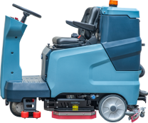
The area figures are screening references, not productivity or shift-completion guarantees. Tank figures are published capacity fields; usable volume and service interruption still require measurement. The E60 is a walk-behind floor scrubber and the E100 and E130 are ride-on floor scrubbers, but the quotation must still identify the supplied battery, charger, settings and complete configuration used for runtime testing.
Buyer evidence checklist
- Approved duty cycle, required net work time, gross window and reserve
- Exact machine, battery and charger identity with nameplate photographs
- Approved charging procedure, start and completion records and charger messages
- Route map, floor, soil, turn count, area or distance and service points
- Brush or pad, solution, recovery and operating settings
- Ambient conditions and any approved battery-temperature data
- Time-stamped raw log for every checkpoint and interruption
- Tank refill, recovery, drain and service-stop records
- Cleaning and residual-water acceptance result throughout the run
- All valid, invalid and failed runs, with no selective omission
- Recharge-turnaround record where next-shift readiness is part of acceptance
- Signed outcome, limitations, corrective actions and retest scope
Limitations
Runtime can change with battery age, chemistry, capacity, charger, ambient conditions, floor resistance, soil, brush or pad, pressure, solution flow, vacuum load, turns, travel behavior, accessories and protection settings. A result applies only to the tested unit, configuration, route and date.
This protocol does not establish battery cycle life, capacity fade, warranty coverage or fast-charge suitability. Those require the exact battery and charger specifications, approved maintenance and charging procedures, and longer-term evidence. External manufacturer data can explain why these variables matter, but it cannot be used as ELEREIN performance.
Related guides
Traceable evidence
Sources and evidence boundaries
These sources separate ELEREIN-published context from external regulatory, safety, inspection and maintenance guidance.
- Supports
- Battery selection, duty-cycle and maintenance considerations for floor-cleaning equipment.
- Boundary
- Battery runtime still depends on the exact battery, charger, load, age, temperature and route.
- Supports
- Battery charging, ventilation and handling safety context.
- Boundary
- The applicable workplace rules and battery manual must be confirmed for the actual site.
- Supports
- Repeatable performance and safety testing context for cleaning equipment.
- Boundary
- A laboratory service page is not a model-level report or certification.
- Supports
- Safety context for commercial floor treatment machines, including scrubbers and sweepers.
- Boundary
- A standard listing does not certify an ELEREIN model or replace the exact declaration, report or manual.
How to use these sources: Use each source only for the safety, testing, regulatory or procurement principle stated in its boundary. External sources do not certify, endorse or validate an untested ELEREIN model.
Official product context