


Questions this guide answers
Primary question: Will solution and recovery tanks cover the main cleaning period without excessive refill and dump stops?
Direct Answer
A floor scrubber's tank cycle is the shorter of its measured usable-solution time and measured recovery-headroom time. Calculate both from a representative route, then add the observed travel, positioning, filling, draining and recording time for every service event. Rated tank capacity is a screening input only: it does not reveal usable volume, solution flow, recovered-water volume or whether a route can be completed inside a cleaning window.
Decision-page companion
Start with the short decision guide
Use the comparison page for machine screening and this calculator for refill, drain and service-time estimates.
Compare Runtime, Tanks, Width and Practical ProductivityScope and assumptions
This method estimates water-related interruption time for a floor scrubber on a defined route. It applies to procurement trials, route planning and post-installation validation. It does not calculate cleaning productivity, battery endurance, wastewater legality or chemical compatibility.
Use the exact quoted machine and normal operating configuration. Run the measurement on representative floor, soil, turns, traffic controls, brush or pad, chemical and operator settings. Follow the machine manual, the chemical safety data sheet (SDS), and facility rules for filling, draining, personal protective equipment and wastewater. If the test route changes, treat the result as a new scenario rather than silently reusing the old rate.
Four boundaries matter:
- Rated capacity is not usable volume. A 90 L label does not prove that 90 L can be consumed before the machine's normal stop point.
- Solution used is not necessarily wastewater recovered. Water can remain on the floor, in hoses or in the system; pre-existing liquid and measurement error can also affect the balance.
- A tank cycle is not battery runtime. The route ends when the first limiting resource or safety condition is reached.
- Service time includes movement. A fast drain does not solve a six-minute diversion to a remote service point.
Define the worksheet fields
Record every input with a unit and a measurement method. Do not substitute a catalog value where the worksheet calls for an observed value.
| Symbol | Field | Unit | How to obtain it |
|---|---|---|---|
Vsu |
Usable solution volume between the approved start and stop marks | L | Measure the volume added or removed between those marks under the normal procedure |
Vrh |
Available recovery headroom at route start | L | Measure the permitted rise from the actual starting level to the approved service or stop point |
Qs |
Measured solution-use rate while actively cleaning | L/min | Divide solution volume used by active cleaning minutes |
Qr |
Measured recovery-volume rate while actively cleaning | L/min | Divide recovery-tank volume increase by active cleaning minutes |
Ta |
Required active cleaning time for the planned route | min | Use a timed route trial; exclude planned tank-service interruptions |
Rf |
Measured fill rate at the actual tap and hose | L/min | Time a known fill volume at the service point |
Rd |
Measured drain rate using the approved drain procedure | L/min | Time a known dumped volume; include any controlled-flow restriction |
Ds |
Total diversion distance per service event | m | Measure route exit to service point and return to the restart point |
Vs |
Measured service-travel speed | m/min | Time the service diversion under normal access controls |
Tf |
Fixed service time | min/event | Observe positioning, connection, disconnection, required rinse and record completion |
Vrh is not automatically the nominal recovery-tank capacity. If the start level is not empty, subtract the measured starting volume. If the exact model uses an alarm, float, shutoff or operating limit, use the manual-defined boundary and verify it during the trial; do not infer the feature from another model.
Measure the two tank limits
Run a representative trial long enough to include normal straight passes, turns and stops. Mark the solution and recovery levels using an approved, repeatable method. Record active cleaning time separately from setup, discussion and service time.
Calculate the rates:
Qs = solution volume used / active cleaning time
Qr = recovery volume increase / active cleaning time
Then calculate the two time limits:
Solution-limited time, Tsol = Vsu / Qs
Recovery-limited time, Trec = Vrh / Qr
Tank-cycle time, Ttank = min(Tsol, Trec)
If either rate is zero, negative or implausible, reject the run and inspect the measurement method. A negative recovery increase may mean that the tank was not measured consistently. A recovery rate greater than solution use can occur when the route contains pre-existing liquid, but it makes that run unsuitable for predicting a dry-route cycle unless the same condition is part of the intended work.
The ratio Qr / Qs can help diagnose inconsistent trials, but it is not a universal recovery-efficiency score. It should never be presented as an ELEREIN measured result without a controlled, approved test method.
Calculate refill and dump events
For a route requiring Ta active cleaning minutes:
Tank blocks required, B = ceiling(Ta / Ttank)
Mid-route service events, N = max(0, B - 1)

Independent refill events, Ns = max(0, ceiling(Ta / Tsol) - 1)
Independent dump events, Nr = max(0, ceiling(Ta / Trec) - 1)
N assumes a combined-service policy: whenever either tank reaches its boundary, the operator returns to the service point and resets both tanks. Ns and Nr show how often each tank would independently reach its limit. Do not add Ns and Nr to estimate visits because some events can coincide. If the site does not reset both tanks, build a chronological event ledger that subtracts solution and adds recovery volume by active minute, then records a visit whenever either remaining margin reaches zero.
These formulas assume the machine starts with the approved solution volume and available recovery headroom. They exclude terminal emptying, rinsing or handover service after the route. Add that terminal event separately when it falls inside the paid shift or site-access window.
For each mid-route event, estimate the volumes at the point where the limiting tank reaches its boundary:
Refill volume per event = Qs x Ttank
Dump volume per event = Qr x Ttank
Use measured event volumes instead when the operator routinely returns earlier, when route sections force a service stop, or when facility rules prohibit carrying wastewater into another zone.
Calculate the service interruption
When filling and draining are performed sequentially, calculate:
Travel time = Ds / Vs
Fill time = refill volume / Rf
Drain time = dump volume / Rd
Service time per event = travel time + fill time + drain time + Tf
Total mid-route service time = N x service time per event
Planned route duration = Ta + total mid-route service time
Do not assume filling and draining can occur simultaneously. Use max(fill time, drain time) instead of their sum only when the site procedure, machine arrangement and observed trial show that both can be performed safely at the same time. Queuing at a shared tap or drain, access permits, lift waiting and wastewater sampling belong in Tf or in separate delay fields.
Illustrative worked example
The following is a hypothetical planning example, not an ELEREIN test and not a product-performance claim.
A facility measures a candidate machine on its representative route. The measured usable solution volume is 78 L, and the recovery tank has 86 L of available headroom at the approved start condition. During a 45-minute active-cleaning trial, the machine uses 72 L of solution and the recovery volume rises by 60 L.
The service-point test records a 13 L/min fill rate and a 20 L/min controlled drain rate. The total diversion from the route to the service point and back is 360 m. The measured travel speed on that diversion is 60 m/min. Positioning, hose handling, a required rinse step and the log entry take 2.5 minutes per event.
Qs = 72 L / 45 min = 1.60 L/min
Qr = 60 L / 45 min = 1.33 L/min

Tsol = 78 L / 1.60 L/min = 48.75 min
Trec = 86 L / 1.33 L/min = 64.66 min
Ttank = min(48.75, 64.66) = 48.75 min
The solution side is the limiting tank. This example uses the combined-service policy, so both tanks are reset at every visit. For a route requiring 150 active cleaning minutes:
B = ceiling(150 / 48.75) = 4 tank blocks
N = 4 - 1 = 3 mid-route service events

Ns = ceiling(150 / 48.75) - 1 = 3 refill events
Nr = ceiling(150 / 64.66) - 1 = 2 independent dump events

Refill volume per event = 1.60 x 48.75 = 78.0 L
Dump volume per event = 1.33 x 48.75 = 64.8 L

Travel time = 360 m / 60 m/min = 6.0 min
Fill time = 78.0 L / 13 L/min = 6.0 min
Drain time = 64.8 L / 20 L/min = 3.24 min

Service time per event = 6.0 + 6.0 + 3.24 + 2.5 = 17.74 min
Total mid-route service time = 3 x 17.74 = 53.22 min
Planned route duration = 150 + 53.22 = 203.22 min
If the facility's cleaning window is 200 minutes, this plan fails by about 3.2 minutes before adding final machine care, queueing or contingency. The response is not automatically to choose a larger machine. The facility can first test a nearer approved service point, divide the route at a natural break, reduce avoidable fixed handling time, or compare another candidate under the same measurement protocol.
Use a repeatable field protocol
- Freeze the machine identity, configuration, chemical, floor zone, operator and date.
- Confirm the approved fill, drain and wastewater procedure before adding water.
- Measure starting solution volume and actual recovery headroom; photograph or record the marks if site policy permits.
- Clean a representative section while separately timing active cleaning and interruptions.
- Measure ending solution and recovery volumes using the same method.
- Repeat the run under comparable conditions. Investigate results outside the buyer's predefined tolerance instead of averaging incompatible trials.
- Measure fill and drain rates at the actual service point, including any flow-control requirement.
- Measure the complete diversion distance and travel time under normal doors, lifts and pedestrian controls.
- Calculate the limiting tank, number of blocks and total service time.
- Run the complete route to confirm or reject the estimate.
Acceptance and failure boundaries
The tank plan passes only when the representative route stays within all buyer-approved limits:
- The solution and recovery boundaries are not exceeded.
- Wastewater is discharged only at an authorized point using the approved procedure.
- The total route, mid-route services, final care and required contingency fit the cleaning window.
- No service diversion creates an unacceptable pedestrian, traffic, lift or contamination risk.
- Repeated measurements remain within the buyer's stated reproducibility tolerance.
- The floor result and recovery condition meet the separate site acceptance protocol.
Stop the trial and escalate according to the site procedure if there is an uncontained leak, uncontrolled foam, an unexpected shutdown, unsafe water trail, damaged hose or connector, abnormal heat or odor, electrical concern, or an unknown alarm. Do not bypass a limit or protection device to finish the calculation.
Connect the calculation to ELEREIN product data
ELEREIN's confirmed E-series tank figures can start a shortlist, but the usable-volume and flow fields in this calculator still require measurement.
| Model | Published solution/recovery tanks | Published baseline runtime | Route-area screening reference |
|---|---|---|---|
| E60 | 50/60 L | 4-5 h | Up to 10,000 m2 under confirmed route conditions |
| E100 | 90/100 L | 5-6 h | Up to 20,000 m2 under confirmed route conditions |
| E130 | 120/130 L | 6-8 h | Up to 25,000 m2 under confirmed route conditions |
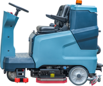
The tank figures are rated capacities; usable volume, drain behavior and protection thresholds require exact-model verification. The runtime ranges are published baselines without published test conditions, not full-load results. The area figures are screening references, not productivity or shift-completion guarantees. E60 is a walk-behind floor scrubber and E100/E130 are ride-on floor scrubbers; confirm the quoted configuration used for the tank-cycle calculation.
Buyer evidence checklist
- Exact model, serial or sample identity and configuration revision
- Representative route plan, active cleaning minutes and cleaning window
- Starting and ending solution and recovery measurements
- Normal brush or pad, chemical, dilution and operator settings
- Fill point, drain point and approved wastewater procedure
- Measured fill rate, drain rate, diversion distance and travel time
- Calculation sheet with units, formulas and rounding
- Full-route result, exceptions, photos where permitted and sign-off
- Separate loaded-runtime, floor-result and water-recovery records
- Current exact-model operating and maintenance instructions
Limitations
This calculator cannot prove chemical compatibility, cleaning quality, residual-water performance, battery duration, legal discharge or model suitability. Flow can change with operator settings, floor resistance, route geometry, soil and machine condition. A result from one route should be transferred only after the new route's conditions are shown to be equivalent.
Related guides
Traceable evidence
Sources and evidence boundaries
These sources separate ELEREIN-published context from external regulatory, safety, inspection and maintenance guidance.
- Supports
- Wet-floor, drying, pedestrian-control and cleaning-process factors relevant to route planning.
- Boundary
- The guidance does not define a universal drying time or approve a machine-floor combination.
- Supports
- Planned maintenance, competent work and safe maintenance arrangements.
- Boundary
- The exact model manual and site safety procedure remain controlling documents.
- Supports
- Repeatable performance and safety testing context for cleaning equipment.
- Boundary
- A laboratory service page is not a model-level report or certification.
How to use these sources: Use each source only for the safety, testing, regulatory or procurement principle stated in its boundary. External sources do not certify, endorse or validate an untested ELEREIN model.